Abstract
Nodes on the road network are the intersections where
traffic changes direction to head towards the desired destination. As a result
of directional changes of the traffic, there are a number of conflict points at
the intersections causing safety concerns. Especially, with different modes
including pedestrians and increasing volumes of traffic flow through the
intersections. Minimising or eliminating
the conflict points at intersections is a continuous process for enhancing
safety, and; a variety of measures are in use or are in study to control the
flow of traffic through signalisation and/or geometrical solutions at grade and
also by grade separation. Bus stops are
normally placed at a minimum distance away from the intersections as per norms
or at mid-block. Grade separation impacts the location of bus stops moving them
towards mid-block and increasing the transfer distance to transit passengers. A
set of conceptual integrated grade separated intersections which laterally and
vertically segregate traffic flows by vehicle size to different levels [’n’
grades - (G 0) Ground, (G -n) Underpass and (G +n) Elevated] with integrated
bus stops to minimise the transfer distance of transit passengers and safe
passage of vehicles and pedestrians is suggested.

Henry Ford II
writing in the introduction to the book on Machines (Life Science Library,
1964, Time Incorporated) stated that Henry Ford I believed in working hard and
not in doing hard work.
It essentially means, man must work hard and let
machines do the hard work.
Translating this to transportation:
“Pedestrians and bicyclists to maintain the same grade
on a road network to the extent possible and, motor vehicles to change grade as
often as required and appropriate.”
The concept includes pedestrian crossings which are at
the same grade as pedestrian or passenger paths and are also integrated with
bus stops at ground and elevated levels. The height of elevated pedestrian
crossings, where necessary, is lower than normal reducing pedestrian effort.
Pedestrian crossing will be during a synchronized signal phase with bus dwell
time.
Pedestrian-vehicular conflict levels, on the two
carriageways and the roadway as a whole,
with bus lanes in the centre as in
BRT systems were compared with those with bus lanes on the curbside
which is the conventional practice. The comparison indicated the advantages of
the curbside bus lanes.
The road
infrastructure which was pedestrian and non-motor vehicle centric leaned
towards motor vehicle or car centric post introduction of motor vehicles in to
the transportation system and less on people centric. With increasing volumes
of motorized traffic in the transportation system, significant developments,
during the last half a century plus period, have taken place in the geometry of
links (road sections) and nodes (intersections). Vehicles, both motorized and
non-motorized, of different sizes and people (pedestrians) are moving on the
road network and the infrastructure is needed to be upgraded, planned and designed
to cater to all. The motor vehicle centric or more precisely car centric
planning, is however, showing signs of shift again towards people centric with
increasing emphasis on non-motorized and mass transport modes. Mode segregation
through dedicated lanes (lateral segregation), such as foot paths, cycle tracks
and bus lanes are in practice with varying level of implementation and
successes across regions. This is to address the safety issues and reduce the
friction created by different class of vehicles on a link to provide an
efficient travel facility. Intersections (or the nodes) are the locations on a
road network where direction of travel changes and the geometry depends on the number
(three or more) of intersecting links. Basically, three or four legged
intersections which are in majority, in most regions, can be conceptually
represented as “Perpendicular Intersections” in the form of a “ᴛ” (T) and “+”
(X) where links intersect with each other at right angles. Though, intersections on ground could be
skewed as well with links intersecting at different angles. Traffic passing
through an intersection experiences diverging, merging and crossing conflicts.
The number of conflicts increases with the increase in number of intersecting
links thereby increasing the risk of collisions. Traffic flow through
intersections with the objective of minimizing the risk of collisions is
managed by different methods of channelization (including rotaries or
roundabouts) and or control measures (manual – police or automatic signaling) depending
on the volume of traffic. The later measures of controlled flow can result in
significant stopped delays at intersections and are not desired by users. This
necessitated the need for vertical segregation of traffic to different levels
(grades) of travel surfaces such as on ground (G 0), over ground (G +n) and
underground (G -n) – “n” the number of level(s) above or below ground – on which
traffic in different directions flows at intersections with high volume of
traffic. Different forms of grade separation schemes (including directional
interchanges) [00], in accordance with traffic
requirements and space availability / constraints, are in practice, both, in
urban areas (arterial roads) and rural areas (inter-city highways). Also, a few
Unconventional Intersection and Interchange Designs (UIIDs) have been
implemented and studied for enhancing the traffic flow and safety through the intersections
[01]. These grade separation facilities including
the simplest of forms in urban areas have an impact on the location of bus
stops. The bus stops are usually planned at a minimum distance away from an
intersection such that the flow of traffic is not impeded. Grade separation
facilities push bus stops farther away from intersections and in some cases to
almost the midpoint of a link between two intersections. This increases the
walking distance of transfer passengers moving over to the bus stop on the
other side of a roadway or any other bus stop on other links of the
intersection.
A set of conceptual grade-separated intersections which laterally and vertically separate
vehicles by size – Buses/Trucks (G 0 or G +1) and Cars / Motor Cycles (G -1
& G -2) – with bus stops on ground (G 0) or elevated (G +1) at the mouth of intersection to
minimize walking distance of transfer passengers is proposed here.
The objective of the concept – an integrated bus stand and grade
separated intersection – is for providing an efficient passenger transfer
facility and also for smooth flow of MV (motor vehicle), NMV (Non-MV) and pedestrian
traffic through the intersection in consideration of the following:
1. Walking
distance of transfer passengers is minimal;
2. Bus
stops are within intersection functional area;
3. Availability of direction
wise bus stop(s) to accommodate maximum number of berths;
4. Pedestrian
and bicycle crossings are integrated;
5. Availability
of bicycle and motor cycle (scooter) parking space to encourage public
transport usage;
6. Drop
and pickup points for personalised owned and hired vehicles;
7. Conflict
between buses and other motor vehicles passing through the intersection is
eliminated;
8. All
grade separated movements to be within the common area
formed of ROW width of intersecting roads;
9. Natural
order - Left, Straight & Right - of traffic flow is maintained even with
grade separation; and
10. Land
requirement other than the ROW (Right of Way) is minimised;
The concerns identified,
and suggestions stated in Optimal Allocation of Road Space [02],
concerning the safe movement of pedestrians, cyclists and passenger access to
bus stops have been an input in preparing the conceptual intersections and the arrangement
of various elements on the links between two intersections.
Grade
Separated Straight Flows
The impact of
grade separation on the location of bus stops in urban areas can be gauged by
the simplest form of grade separation in which straight flows on one or both
the axes of an X-Intersection are assigned to different levels and turning movements
are retained at ground level and are signal controlled. Such a facility is a
common practice in India.

The design parameters which impact the location of bus stops are:
1.
Minimum Distance between Intersection and
Bus Stop [03] – 75 m
2.
Minimum Vertical Clearance (MVC) in Urban
Areas [03] – 5.50 m
3.
Maximum
Height: Single deck vehicles [04] – 3.8 m
4.
Maximum
Height: Vehicles carrying Freight Containers [04]
– 4.2 m
5.
Double
decker [04] – 4.75 m
6.
Maximum
Gradient for Urban Roads with slow moving traffic [03]
– 2%
7.
Maximum
Gradient for approaching viaducts / earth embankments [05]
– 3.5%
8.
Maximum
Gradient for Urban Roads [03] – 4%
MVC suggests
that the travel surface of a grade
separated flow will be about 7.5 m above or below the flow on ground assuming a
deck depth of 2 m (Design dependent) of the structure for which MVC needs
to be maintained for serving the vehicles of different heights. Thus, a ramp length of about 225 m would be
required to connect the grade separated travel surfaces to the ground level
assuming a slope of 1: 30 (3.33%)
within the guideline limit.
Impact of Grade Separation (IGS)
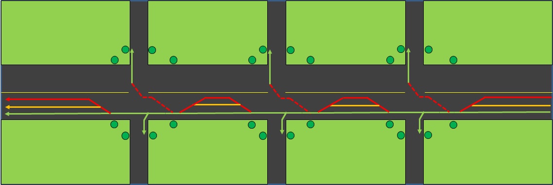
IGS (Passengers) - The bus stops are normally positioned at locations
shown in GREEN on a conventional X-intersection with all
movements on ground. However, grade separation necessitates the bus stops to be
positioned at locations marked in RED. Thus,
walking distance will increase for the transfer passengers. Passengers do
get some relief, when the bus stops, for buses turning left or right, are
positioned at locations shown in YELLOW approximately
midway between the other two locations or a point towards the intersection
close to the start/end of ramps serving the grade separated flows.


The movement of buses between intersections at grade on a road network is typical to that of other motorized vehicles in the section. That is, they weave between inner and outer lanes (excluding rash or dangerous driving) as do other traffic. However, their large size does affect the flow of other vehicles, especially in an urban network, when they weave in to and out of the bus stops located on the outer lane. The affect is felt more at the bus stops on the intersection exit side than those at intersection entry side. For, on the intersection entry side traffic is normally slowing down closure to the intersection for a possible halting at the signals, if any, or changing lanes to turn as appropriate and move cautiously through the intersection. On the other hand, at intersection exit side the affect is more; for, traffic is just then leaving the intersection post a possible halting for signals and on the speed increase phase which is interrupted by a bus weaving in to or towards the inner lane. Ideally if the buses move only on the outer lanes along the paths shown in green (bus lanes) and not along paths shown in yellow or red; the interference with the other traffic is eliminated on intersection exit side and; at the intersection entry side, is minimized or reduced to the one concerning right turning buses only. However, the concept of bus lanes is not successful in some urban areas.
In a grade separated case the right turning buses do not significantly affect the flow of other turning traffic as it is already moving slow on the slip roads and approaching the usually signalized intersection. However, the buses weaving from a ramp towards a bus stop or those weaving towards a ramp, especially between two sequential ramps significantly affect the flow of other traffic. Impact is felt more by the traffic that is likely or weaving between lanes while approaching a ramp or moving down the ramp to complete the desired maneuver.

Bus Rapid Transit (BRT)


However, if a
BRT corridor is along a path on which a flyover (or in general a grade
separated facility) exists, or is in planning, weaving conflict is likely to occur
depending on which traffic – buses or motorized vehicles – will use the flyover.
If it is motorized vehicles, one of the options is discontinuation of BRT
corridor prior to the beginning of the up ramp allowing appropriate weaving
length for buses to enter the bus stop below and adjacent to the flyover and
the other traffic to access the flyover. The BRT corridor continues after an
appropriate weaving length, to permit the traffic to
switch lanes to the
desired position on the road surface, at the end of the down ramp of the
flyover. That in effect results in a
weaving conflict between buses and other traffic at entry/exit ramps of the
grade separated facility. An alternative to eliminate the weaving conflict is
to extend the flyover on the hatched green sections with desired Minimum Vertical
Clearance and the up/down ramps positioned in the light green sections for
uninterrupted movement of vehicles using flyover. Another option is a split
flyover for the two directions along the light green axes such that the bus
stops are located under the flyovers and buses move with no deviations.


The mid-block bus stops with bypass lane option could be parallel or
staggered depending on space availability. It is necessary to provide
pedestrian crossing facilities at both ends of mid-block bus stops for
passengers to access the same safely. However, in case of parallel and low
passenger demand at a mid-block bus stop only one pedestrian crossing facility
can be considered [07]. In the case of staggered
mid-block bus stops pedestrian crossing facilities necessarily be provided at
two locations. Thus, the other traffic moving on the link would have to stop at
one or two pedestrian crossing facilities in addition to the stoppage at
intersections causing additional delays and increasing journey times. Grade
separated pedestrian facilities (subways or foot over bridges) would address
this delay issue.

BRT Bus Stop Location Impact


Concept
The concept assumes lateral
and vertical segregation of vehicles by size, essentially, the height of
vehicles for safe and efficient movement of pedestrian and vehicular traffic
through an urban arterial intersection.
The space standard or right of way (ROW) for urban
arterial has been increased from 50-60 meters [03 & 05]
to 50-80 meters [08]. The widths for different
cross-sectional elements for the concept intersection are based on the
information in various guidelines [03, 06 & 08].
The assumed dimensions of cross-sectional elements on
arterial road are:
1. Motor vehicle lanes 3
per direction x width 3m x directions 2 = 18m
2. Bus lanes 2
per direction x width 3.5m x directions
2 = 14m
3. Median width = 4m
4. Motorway width = 36m
This leaves a width of ROW range of 24m to 44m based
on the respective upper limits (60m and 80m) of the space standard(s) range in 03 and in 08. This
residual range of ROW can be utilised judiciously for the development of segregated
supporting or auxiliary infrastructure such as foot paths (sidewalks), bicycle
tracks, service roads, parking and drop/pickup points as required on both sides
of the motorway.
The concept is developed considering
buses to move, in physically segregated lanes, either in outer lanes as in the
conventional bus system or in the central lanes as in BRT systems. In both the
concepts buses can move rapidly as they are laterally and vertically segregated
from other traffic. Trucks, or in general Heavy Motor Vehicles (HMV) including
private or institutional buses, can also use these lanes prioritized for buses,
during specified periods or throughout subject to capacity constraints and
safety of bus passengers.
|
As stated in an earlier
section maximum height of single deck vehicles, which includes buses and
trucks, is 3.8 meters and that of double decker bus is 4.5 meters. Minimum
vertical clearance required for Light Vehicles is 3.5 meters for an
underpass [09]. The concept is based on this
information and that most of the passenger vehicles (except double-decker and
some category of large buses) and; some trucks (except large trucks) are observed
to be less than 3.5 meters in height [10, 11] and do not require vertical clearance of 5.5
meters. Such vehicles can be classified as Small Motor Vehicles (SMV). SMVs in the concept are suggested to pass
through the intersection using a network of subways at two different levels
(G -1) & (G -2) with a vertical clearance of 3.5 meters.
|
SMVs right turn manoeuvres will be through an adapted
Michigan Left (or Median U-Turn - MUT) [12]
for LHT (Left Hand Traffic) regime
and grade separation maintaining natural order of traffic flow at an intersection.
MUT is an at grade intersection in which left
turns in an RHT (Right Hand Traffic) regime are disallowed. The left turns are
accomplished through a combination of right turn, followed by U-Turn and
straight through or; straight through, followed by a U-Turn and a right turn as
per the hierarchy of intersecting roads.

The vertical clearance of 3.5
meters for SMVs suggest that the travel surface of the subway at (G -1) level
will be 5.5 meters below ground, assuming a deck depth of 2 meters, and; that
of the subway at (G -2) level would be 11 meters below ground. The starting
point of the ramps that connect the travel surface on ground with the travel
surface of subways at (G -1) level will be 165 meters (RL) away from the edge
of the intersection service area where the requisite vertical clearance is
warranted with an assumed slope of 1:30 (3.33%) and; that of the ones that
connect travel surface of subways at (G -2) level will be 330 meters (RL) away.
The weaving section (WL) of the concept intersection is assumed to be 150
meters in length based on the guideline value of 300 meters desired length and
minimum length of 200 meters between entry and exit terminals of an interchange
[14]. The other half of 150 meters of the
desired weaving length of 300 meters will be part of the functional length of
the intersection on the other side of the road section under consideration, if
midblock is absent (ML = 0). The presence of midblock (ML > 0) enhances the
efficiency of sectional traffic flow.
Service length (SL) depends on
the length of buses. The length of regular (‘R’) buses is 12 meters and that of
the trailer (‘T1’) buses is 18 meters or 25 meters (for bi-articulated – ‘T2’)
[10]. The concept is planned to accommodate the
three sizes of buses, with doors on both sides, for universal application.
Channelizing islands to be compatible with the size of bus stops to be housed.
Larger the bus stop size,
larger will be SL and would impact ML of a section of road between two
intersections. The minimum distance between intersection and bus stop [03] may be considered upper limit for SL (<= 75 m)
of the concept. That is, bus stops are suggested to be within 75 meters of an
intersection against the current norm of at least 75 meters between
intersection and bus stops.

The assumptions indicate FL of
a concept intersection on the side with a short ramp (from G -1 level) is
likely to be about 400m and; on the side of a long ramp (from G -2 level) would
be about 600m. This suggests that the minimum intersection spacing required would
be in the range 800 to 1200m depending on the combination of ramps on the
interconnecting road section between two intersections. Of course, the range
may vary in accordance with or to meet the design norms. The recommended
intersection spacing on arterial roads in urban areas is less than 1.5 kms in
central business districts and about 8 kms in urban fringes [03]. The corresponding values for sub-arterial roads
are 0.5 km and 3 to 5 kms respectively. The urban arterial road network is
sparse in India and the average range of intersection spacing is 800 to 1900
meters in Delhi [06]. It may thus be possible to
consider the concept on Indian road network. The concept may be more feasible
in green field cities being planned and; in smart cities, especially with a
greenfield option as the intersection spacing can be decided at the network
planning stage. The minimum intersection spacing required for the concept
intersection is marginally over one kilometer when two long ramps are in
sequence or on the same axis of movement.
Concept with BRT in
Central Lanes
The fact of developing a rapid bus corridor is to encourage use of
public transport. This usage can be further enhanced by quick access facilities
such as dedicated footpaths for public transport users. Such a facility, which
can be part of Multi-Utility Strip [06]) adjoining
the edge of the carriage way, can also be used for pickup and drop services of
the likely public transport users. And the one on the edge of ROW is for the
rest of pedestrians who access the abutting economic activities. The
pedestrians on exiting a building need not come into conflict with cyclists or
service road users and safely walk on this footpath for other tasks. Those who
use public transport can wait on this and observing for appropriate gap in the
movement of cyclists and service road users can cross over to the other
footpath for accessing public transport.

01
Buses in all directions in either of the formats of a
conventional system or as in BRT move at (G 0) level.
02
Channelizing islands and quadrants be designed to
accommodate bus stops for buses moving straight and turning left.
03
Bus stops for buses turning right may be provided on
the medians with adequate size at the mouth of intersection.
04
Bus lanes at mouth of intersection to be widened to
facilitate express buses pass through a priority signal while others are in
service at bus stops.
05
Trucks
to use the Bus Lanes during designated hours.
06
All left turns are performed at (G -1) using the ramps
on the LHS of the carriageway.
07
North-South-North straight moving traffic pass through
intersection at (G -1) using ramps in the central lane.
08
South-East right turning traffic goes down the ramp on
RHS to (G -1) continues at the same level till past the beginning of down ramps
from north and makes a U-turn adjacent to the outer lane and merges with the
left turning traffic from North to East and completes the right turn.
09
Similar movement for North-West right turn.
10
East-West-East
straight moving traffic pass through intersection at (G -2) using ramps in the
central lane.
11
West-South right turning traffic goes down the ramp on
RHS to (G -2) continues at the same level till past the beginning of down ramp
for left turning traffic from east. It then moves on the loop at (G -2) for
U-turn under the ramps going down towards west and completes U-turn adjacent to
the outer lane. It then moves up the ramp to (G -1) and merges with the left
turning traffic from East to South and completes the right turn.
12
Similar movement for East-North right turn.
13
On approach sections to the intersection, Right
Turning traffic, like in conventional at grade intersections, can continue to
move or weave in to the inner lane to perform the right turning manoeuver. This
is like dedicated left turn bypasses concept in a “Four-Flyover Roundabout” for
a RHT regime traffic [15].
14
Buses and Trucks (HMVs) can access the adjoining zones
through service roads and their connectors to the HMV Lanes.
15
Buses dwell time to be integrated with signal cycle
and phasing to provide safe pedestrian crossing time slots.
16 Both sides of the roadway are suggested to be equipped
with two segregated footpaths each of width appropriate for demand or of a
minimum width as per norms for free flow of pedestrians and easy access to bus
stops.

Bus stops with desired number of berths for buses moving in each of the
three directions be designed in conjunction with design of (or housed in) channelizing
islands and median in the intersection functional area. Thus, optimizing the space required for bus
stops and minimising or eliminating land acquisition issues. Integrate pedestrian
crossing facilities with bus stops such that passengers and pedestrians can
crossover to the desired immediate destination(s) during the dwell time of
buses at berths.
The number of vehicles
(buses) with a potential for a conflict entering the intersection area are
limited with only straight moving and right turning ones. Also, they enter the
intersection area post boarding and alighting (dwell time) operations at the
bus stops akin to stop, look and go traffic rule. Express buses can also follow
this rule for safe maneuver through the intersection area. However, flow of
buses to bus stops or express services which pass through them are to be
controlled by traffic signals to permit safe passage of passengers on
pedestrian crossings as they are placed behind the stopped buses. Thus, the
intersection operates as a partially controlled one.
The buses exit
from bus stops may be planned by synchronizing bus door closure and another set
of traffic signals in front for greater safety of bus flow through the
intersection area. Such an arrangement will be akin to trains passage
through railway stations.
BRT (or Bus) Lanes – Curb v/s Median side
BRT, a
relatively recent development, addressed the weaving conflicts of buses and
other motor vehicles on a roadway. It is mostly placed in the central lanes – median
side (Alternate Option – AO). So
naturally the bus stops that serve the passengers are in the center of the
roadway unlike as in a conventional bus transportation system, predecessor to
the BRT system which is in operation in parallel or otherwise, in which bus
stops are located adjacent to and on the outer edge of the outer lanes - curbside
(Base Option – BO).
Crossing Pedestrian Volume - Passengers accessing the bus stop in Alternate Option
are necessarily to cross the roadway twice, once towards it and once more away
from it. However, in Base Option passengers had an option of not crossing the
roadway while moving to or from a bus stop if it is on the same side of their
origin or destination respectively.

Assume N


Pedestrian Vehicular Conflict - Pedestrian-Vehicular Conflict (PVC)
is measured by the expression, PV2 (where, P = Pedestrian volume and
V = Vehicular volume) [16]. The PVC value on the
northern carriageway is higher than that on southern carriageway, in Base
Option as vehicular volume is higher on northern side. So also, in Alternate
Option Case-1, as passenger and vehicular volumes together are higher on the
northern side. The higher and lower PVC values of the two carriageways in
Alternate Option Case-2 switch from one side to the other depending on the
values of independent parameters “p” and “K” which respectively compute the lower
passenger and vehicular volumes.

PVC difference
between carriageways for all options are as given below.
Base Option: (1+p)NV2 - (1+p)KNV2 = (1-K)(1+p)NV2
Alternate Option
Case-1:
Alternate Option
Case-2:
Base Option v/s Alternate
Option Case-1:
The difference in PVC of the two carriageways in Base Option is less than that of the PVC difference in Alternate Option Case-1 as shown hereinafter.
The difference in PVC of the two carriageways in Base Option is less than that of the PVC difference in Alternate Option Case-1 as shown hereinafter.
(1-K)(1+p) - 2(1-Kp) = 1 - K + p - Kp - 2(1-Kp)
= (1+K)(p-1)
≤ 0 for (p-1) ≤ 0
This suggests that in Base
Option pedestrian crossing risk level on one carriageway is similar or close to
the risk level on the other carriageway of a roadway as against higher risk
level on one carriageway in comparison to the risk level on the other
carriageway in Alternate Option Case 1.
Base Option v/s Alternate
Option Case-2:
The difference in PVC of the two carriageways, (1-K)(1+p)NV2, in Base Option could be higher or lower than the corresponding difference in Alternate Option Case-2 expressed by (p-K)2NV2 for (p-K)
The difference in PVC of the two carriageways, (1-K)(1+p)NV2, in Base Option could be higher or lower than the corresponding difference in Alternate Option Case-2 expressed by (p-K)2NV2 for (p-K)
(1-K)(1+p) - 2(p-K) = 1 - K + p - Kp - 2(p-K)
= (1-p)(1+K)
≥ 0 for (1-p) ≥ 0
That is, (1-K)(1+p) ≥ 2(p-K) is true only when (p-K) ≥ 0. This is evident from the positive values in the upper triangle of the
matrix as also that of the values in the diagonal cells. Further, some cells in
the lower triangle (when (p-K) < 0) are positive a characteristic of
absolute differences. This indicates that Alternate Option Case 2 has lower PVC
difference between carriageways than that in Base Option for more than half the
traffic scenarios in Alternate Option Case 2. However, many cells in lower
triangle are negative indicating Base Option has lower PVC difference between
carriageways than that in Alternate Option Case 2 for certain traffic
scenarios. That is in this case (Alternate Option Case 2) pedestrian crossing
risk levels on the two carriageways is similar or close only in limited traffic
scenarios and not in all.

Base Option v/s Alternate
Option: The difference in the PVC values of the two carriageways, in the
overall, in majority of traffic scenarios (vehicular and pedestrian volumes), is
lower in the Base Option in comparison to the differences that are likely in
both the cases of Alternate Option. This is, primarily, because in Base Option
PVC difference between carriageways is dependent on the variations in vehicular
volumes only as crossing pedestrian volume is same on both the carriageways
irrespective of different passenger volumes generation on the two sides of the
roadway. Whereas, in Alternate Option, PVC level on the two carriageways is
dependent on the variations of passenger and the resultant pedestrian volume
generated on either side of the roadway as also the variations in vehicular
volume which is resulting in the PVC difference between carriageways to be higher
in majority traffic scenarios than that in Base Option. That is, crossing pedestrians are exposed to similar
or close conflict levels on both the carriageways in the Base Option unlike
significantly different conflict levels in the case of the two cases of Alternate Option. Further, the system
introduced bias, in the Alternate Option, of exposing pedestrians generated on
one side of the roadway to significantly higher conflict levels than those that
are generated in the other side, is eliminated in the case of Base Option. This
suggests, that Base Option has an
advantage over the Alternate Option from the pedestrian safety perspective.
Roadway PVC: Aggregate PVC level
on the roadway in the Base Option is the average of the aggregate PVCs of the
two cases of Alternate Option and; Case-2, has the least aggregate PVC value as
high pedestrian volume and high vehicular volume are on different carriageways.
That is,
[2(1+Kp)NV2 + 2(K+p)NV2
] / 2 = (1+Kp+K+p)N
V2 = (1+p)(1+K)NV2
and;
Alternate Option Case 2
2(K+p)NV2 |
Base Option
≤ (1+p)(1+K)NV2 |
Alternate Option Case 1
≤ 2(1+Kp)NV2 |
[for, K ≤ 1 and p ≤ 1 ⇒ K+p ≤ 2 and Kp ≤ 1 ⇒ (K+p)-Kp ≤ 1(=2-1)
⇒ (K+p) ≤ (1+Kp)]
This suggests that the directional volume (DV) significantly impacts the aggregate PVC values in Alternate Option from low to high between cases while DV has no impact on the aggregate PVC value in the Base Option. This further suggests that Base Option is stable considering the aggregate and directional distribution of PVC and thus has an advantage over the Alternate Option.
Concept and PVC: Grade separated
pedestrian facilities (underpasses or bridges) can eliminate PVCs but crossing
pedestrians resist their usage and risk crossing the roadway at grade. The
resistance is due to the associated social risks in grade separated facilities,
especially in less frequently used ones and; the need to walk additional
distance to access them or to climb to a height which maintains MVC necessary
for the movement of large vehicles.
The concept considers both at
grade and elevated (safer and more acceptable than underpass) pedestrian
crossing facilities which would appeal to the users. The concept considers reducing
the height of an elevated crossing – by reducing MVC from 5.5m to 3.5m – an impediment
for the use of pedestrian bridges. Pedestrian bridge’s usage can be enhanced
through integrating them with bus stops through such facilities as provided by
metro systems.
Bus Lanes Placement – BRT is developed as an open or
closed system and mostly the bus lanes are placed in the center of the roadway
on median side. BRT-CS (Closed System) is a dedicated system exclusively for
buses, or routes to be specific, operating in the system. Although emergency
vehicles can use the lanes in some systems, other buses (such as, school,
institutional and chartered buses including bus routes operated by conventional
bus systems) are prohibited from using BRT lanes. In such cases a complete
segregation of SMVs and HMVs is not achieved. That is, the friction or conflict
between HMVs and SMVs is only reduced but not eliminated. Use of BRT lanes by
other mass transport vehicles – that is BRT-OS (Open System) – enhances the
level of service of other buses and utilization of the BRT lane, which may
remain underutilized otherwise, although, such utilization impacts the rapidity
of the closed system to certain extent. In a centrally placed bus lanes system
– closed or open – mass transport vehicles entering the bus lanes at access
points may queue up in the intersection area in case of exit side island or
split bus stops. Queueing up in the intersection area is eliminated by placing
bus stops on the entry side of an intersection resulting in split bus stops by
direction and no possibility of an island type bus stop. In the curbside bus
lane system also queueing up in the intersection will occur in case of exit
side bus stops suggesting that it is advantageous to place the bus stops on the
intersection entry side.
Bus Stops: In both the cases –
central or curbside – bus lane systems with bus stops placed at the mouth of
the intersection, at the median location or on the corner of the intersection
entry side corresponding to the system in place, the transfer passengers will use
at grade pedestrian crossings connecting the four corners to move between bus
stops. In case the intersecting roads are of same width, comparable transfer
distances would be same in both systems. However, in the alternative, transfer
distances between adjacent bus stops will differ by, a negligible length of,
half of the difference in the widths (a and b) of the two intersecting roads
and remain same for the pairs on the opposite side.
Bus Stops – Center:
Adjacent stop
transfer distance is (a/2 + b/2) and to opposite one is (a/2 + b + a/2)
Bus Stops – Curbside:
Adjacent stop transfer distance is (a or b)

Ground Level Space Utilization:
The
traffic islands in urban areas guide the flow of traffic through the
intersection for safe maneuver of both pedestrians and vehicular traffic. That
is, traffic islands function as channelizing islands for vehicular traffic to
change direction of flow or safe passage of opposing flows and; as storage
(collection and dispersal areas) and refuge areas (mid stage of crossing; if
necessary) for crossing pedestrians. The
size of the traffic islands at the corners of an intersection can be increased
and put to an additional use – Bus Stops – at the mouth of the intersection on
entry side and to accommodate bicycle crossings adjoining pedestrian crossings.
The bus stop on straight edge of the channelizing island is for straight moving
and right turning buses and that on the edge on hypotenuse for left turning
buses. That is, in the case of bus lanes on the curbside; two sides of
channelizing islands can be used as bus stops. Whereas, in case of bus lanes in
the center, in accordance with the current practice, median width at the mouth
of the intersection needs to be increased to function as a bus stop and will require
a larger size in length to accommodate the same number of buses, as in this
case only one side would be available for use as bus stop, unlike two in the curbside
one.

Additional number of lanes are
introduced at the mouth of the intersection to provide storage for turning
vehicles. This additional space could perhaps be more effectively utilized by
integrating with the bus lanes and bus stops suggested on the channelizing
islands and; the width of the regular lanes be considered for SMV use only. An
arterial roadway is normally either a 2x2 (12 m wide – with 3m lane width for
SMVs as suggested earlier) or 2x3 (18m wide) lanes system with a median of
appropriate width. An 18m width of SMV lanes in the center of the roadway,
enveloped by bus lanes on both sides, is sufficient to function as a median of adequate
width for buses to make a U-turn from inner to inner lanes of the physically
segregated curbside bus lanes on both the carriageways of the roadway through a
compatible signal phasing system. A 2x2 lane system can consider a median of 6m
width or, for a more effective use, storage lanes of same width for turning
vehicles. These lanes will provide minimum lateral separation (18m) for inner
bus lanes on both the carriageways to facilitate U-turn of buses. SMVs can
perform U-turn, if so desired, around the rotary during the same signal phase
which permits SMVs to pass through the intersection. SMV lanes can be depressed
to (G -1) and (G -2) levels and connected to accommodate all the turnings that
exist on the ground level as suggested in an earlier section in case grade
separation is warranted or, even otherwise, considered for enhancing the
utilization of the space at ground level. The space thus released at ground
level could be utilized for housing a bus stop for right tuning buses and appropriate
infrastructure for bicycle and motor cycle parking. Direction oriented bus
stops are thus possible with a geometric arrangement as conceptualized. In a
grade separated central bus lanes option also channelizing islands can be
planned to accommodate bus stops for left turning and straight moving buses with
SMV lanes running underneath and a bus stop on the median for right turning
buses to provide direction-oriented bus stops. However, median would have to be
widened substantially to accommodate bike parking infrastructure and to
facilitate buses to U-turn.

Signal Phasing – Base Option: Conventionally
traffic flow through an intersection is controlled by time segregation of
conflicting flows by a signaling system or by a rotary eliminating conflicting
flows and converting the same in to merging and diverging flows. Flow through
certain over utilized rotary intersections is also controlled by police or through
an appropriate signal phasing to minimize weaving conflicts. That is, in later
case, two methods are in simultaneous operation to control the flow of traffic
through an intersection. Bus priority
signal phasing was adopted with the introduction of BRT systems on the
corresponding corridors. Pedestrian movement along the periphery of the
intersection and across is permitted through an all red phase for vehicular
flow through the intersection or by synchronizing pedestrian phases along
certain directions on the periphery with vehicular phases by direction
combinations such that the vehicular flows are not in conflict with
pedestrians. Essentially, the two categories of flows – pedestrian and
vehicular – are considered currently for planning of signaling systems.


It may be appropriate,
instead, to consider three categories of traffic – pedestrian, SMV and bus –
flows that pass through the intersection for the planning of signaling systems and
accordingly time segregate by categories, rather than by directions, in the
case of an at grade intersection with a rotary arrangement and curbside bus
lanes. It is assumed that the total combined dwell time of all the buses in a
bus stop – 3 bays – would be about 30-45 secs. A signal cycle time greater than
120 to 150 secs range is not desired considering the behavioral aspects of road
users although there are many signalized intersections in operation in India with
signal cycle time more than the desired limit. A 4-phase signaling system with
a cycle time range of 120 to 150 secs is suggested with each phase catering to
a flow category and not to a flow by directions. That is, a single category of
vehicles negotiates the rotary in an assigned phase to pass through the
intersection. The conceptualized phasing plan with the suggested cycle time range
and broad phase times is – Phase-1 (Pedestrians – 30-45 Secs), Phase-2 (Buses –
30 Secs), Phase-3 (SMVs – 30-45 Secs) and Phase-4 (Buses – 30 Secs) coordinating
pedestrian and SMV phases with buses dwell time. It is assumed that pedestrians
will cross, at a walking speed of 1.2 m per second, between curbs, spatially
separated by 36 m, in two stages with a break on the median, if necessary, which
is about 16 m from a curb edge. That is, every alternate phase even across
cycles will serve buses flow giving a priority to their passage through the
intersection. The Phase-4 a second phase for buses in the same cycle was
introduced, post completion of boarding/ alighting activities during the SMV
phase, in to the signal cycle, to eliminate the idle waiting time of buses and
passengers, during the pedestrian phase of the following signal cycle in a
3-phase signaling system.


A similar signal phasing
option may be considered at an at grade intersection on a central bus lane BRT
system minus directional bus stops, on each approach arm, and busses to maneuver
around the rotary for a U-turn.
The number of phases in a
signal cycle can be reduced from four to two with grade separated flows for
SMVs when warranted. The pedestrian phase will be ON during the dwell time of
buses, that is, when bus phase is OFF. Alternatively, the two phases
– pedestrian and bus – are to be synchronized with bus door closure by an
appropriate communication technology, like metro systems, between buses and
signal equipment for an optimal flow of both pedestrians and buses through the
intersection. This allows the buses which have completed the boarding /
alighting activities to exit bus stop and enter the rotary to exit the
intersection at the earliest and let the queued buses to enter the bus stop and
be served minimizing the wait time of buses.
In urban areas where high speed bus corridors
are in consideration ab initio it would be worth considering physically segregated bus lanes on the
curbside in view of the inherent positives of such a system.
References:
00
Interchange
(road) - Wikipedia, the free encyclopedia
01
Marco, Guerrieri et
al. (2013). An International Review on One and Two Level Innovative
Unconventional Intersection and Interchange. ARPN Journal of Engineering and
Applied Sciences
02 Gidugu, Varadaraj. (2014). Optimal
Allocation of Road Space (OARS) – A Concept. Research Gate
03 IRC:86-1983 - Geometric Design Standards for
Urban Roads in Plains
04 IRC:3-1983 - Dimensions and Weights of Road
Design Vehicles
05 IRC: SP:90-2010 Manual
for Grade Separators & Elevated Structures
06 Bus
Rapid Transit Planning Guide June 2007
07 EMBARQ: Draft - Road Safety Design
Guidelines for Bus Rapid Transit in Indian Cities
08 URDPFI Guidelines Volume-1 2015
09 IRC: SP:84-2014 Manual of Specifications
& Standards for Four Lanning of Highways through Public Private Partnership
10 MOUD, GOI: Recommendatory Urban Bus
Specifications – II April 2013
11 Premier Road Carriers Ltd – Road Cargo
Transportation in India
12 Michigan Left (MUT)
13
FHWA - Access
Management in the Vicinity of Intersections
14 IRC:92-1985 – Guidelines for the Design of
Interchanges in Urban Areas
15 Tomaz Tollazi et al. (2015). Environmental, functional
and economic criteria for comparing “target roundabouts” with one- or two-level
roundabout intersections. Research Gate
16 IRC:103-1988 – Guidelines for Pedestrian
Facilities
No comments:
Post a Comment